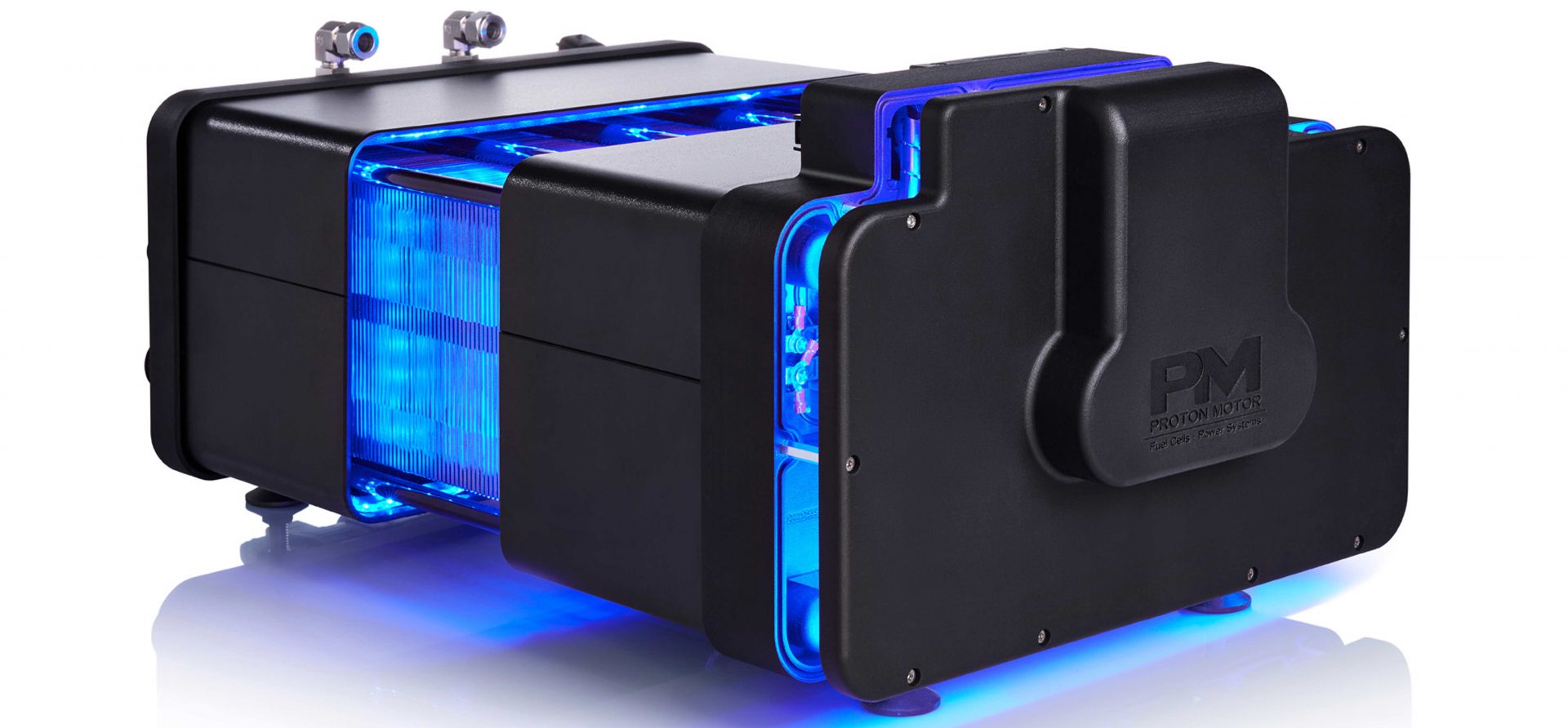
The combined use of electricity and waste heat (combined heat and power) results in a very good utilisation of the originally used primary energy carrier hydrogen. If this hydrogen is produced by using renewable energy sources (e.g. by electrolysis of water using solar or wind power), the entire system is CO2-neutral and emission-free. Only pure water is produced as a reaction product of the fuel cell.
Hydrogen + Oxygen → Electricity + Water + Waste Heat
A fuel cell is a device that converts the chemical energy bound in the molecular bonds of hydrogen and oxygen into electrical energy. In the PEM technology (PolymerElectrolyteMembrane), gaseous hydrogen (H2) is used as a fuel and is reacted with oxygen (O2) from the air to pure water. Other reaction products in the cell are electricity and heat.
In contrast to conventional internal combustion engines, coal-fired power plants and nuclear power plants, no toxic, radioactive or climate-damaging by-products are produced or emitted.
If the hydrogen used comes from renewable sources, for example, by electrolysis of water with electricity generated from wind or solar energy, this technology is completely CO2-neutral.
This makes the fuel cell an ideal component of a sustainable energy supply today and in the future.
Core components of a PEM fuel cell are the so-called bipolar plates (BPP), gas diffusion layers (GDL) and the electrochemically active catalyst layers, which are coated on both sides of a polymer electrolyte membrane (CCM).
The purpose of the bipolar plates is to guide the reaction gases (hydrogen and oxygen) uniformly over the entire active area to the catalyst layer via a specific channel structure (the flow field). A bipolar plate, as the name implies, consists of the two poles of a single fuel cell: the hydrogen-carrying anode plate (the negative (-) pole) and the cathode plate (the positive (+) pole) for supplying the reaction air. In between, a further cooling flow field for the removal of reaction heat is integrated. Another purpose of the bipolar plate is the removal of the resulting reaction water from the chemical reaction.
The gas difussion layer (GDL) between the bipolar plate and CCM is responsible distributing the reaction gases evenly from the channels of BPP on to the catalyst layer of CCM and the removal of product water from the catalyst into the channels of BPP.
The few μm thick polymer electrolyte membrane has the task of separating the two gas spaces (H2 and O2). For this purpose, it is largely gas-tight and electrically insulating, but can very efficiently transport protons and water.
On both sides of the membrane are thin layers of a catalyst, that allow the reactions of oxygen and hydrogen at the low temperatures prevailing in the fuel cell. Small amounts of platinum metal (< 1 mg/cm2) are generally used as the catalyst material.
The catalyst-coated polymer electrolyte membrane is thus the heart of a fuel cell, because it is here that the actual electrochemical reaction takes place, consisting of the two partial reactions:
Anode: 2 H2 → 4 H+ + 4 e–
Cathode: O2 + 4 H+ + 4 e– → 2 H2O
_______________________________________
Total: 2 H2 + O2 → 2 H2O

On the anode side protons (H+) and electrons (e–) are separated. As the protons pass through the polymer electrolyte membrane to the cathode side, the electrons are forced through an external circuit. This creates an electrical potential and the electrons can perform (electrical) work along their path.
On the cathode side, the protons along with the electrons react with oxygen from the air to form pure water when the circuit is closed. As the reaction is exothermic, the heat of reaction can also be extracted from the cooling liquid.
In order to achieve greater performance and to be able to use the fuel for energy supply on meaningful levels, several of these individual cells are connected in series to form a fuel cell stack. Here, each bipolar plate represents the cathode of one cell and the anode of the subsequent cell. This in turn represents the heart of a fuel cell system.
The active area of a cell determines the current of the fuel cell stack by the number of simultaneous reactions and thus the amount of flowing electrons. The corresponding voltage results from the number of connected individual cells.
In addition to the specific design of the individual components, Proton Motor Know-how also includes the construction of a complete fuel cell system around the core component cell stacks.
The stack is embedded in a module consisting of hydrogen, cooling and air management components as well as hardware and software and a sophisticated safety concept. Due to the modular structure of the Proton Motor fuel cell stack, simple integration into a higher-level system is possible. This allows us to address the diverse conditions in stationary, automotive or maritime applications, resulting in a tailor-made concept for the respective use.
Advantages of fuel cell technology:
- No harmful emissions
- High efficiency
- Use of waste heat possible
- Low noise
- No vibration
- Low wear of the components
- With off-grid or emergency power supply, the bridging time is limited only by hydrogen supply (tank capacity)
- Fast refuelling possible (unlike batteries)
